
|
Welcome to Gary's Imaginarium, From Dreams to Reality. |
Transcript from Revolutionizing PEMF Devices: Unveiling the Healing Waveform - 2024

|

|
As this banner suggests, whether you're a PMT practitioner or a builder of Pulsed Electro Magnetic Field, or PEMF devices, this video will take you through our discovery of the healing waveform and how you can ensure your PEMF devices are emitting it. For newcomers to PEMF, I'll briefly define it before we go into how we discovered the Healing Waveform. Additionally, we'll take you through the building of a PEMF device and share the results of our testing. |
|
|

|
I am Gary's personal assistant Paula, and I would like to welcome you to Gary's Imaginarium channel. From dreams to reality. We will be covering all sorts of topics from 3D printing, CNC machining, Laser engraving and lots of electronics projects. |
|
|

|
Today's topic is PEMF or Pulsed ElectroMagnetic Field devices. A PEMF device is used in Pulsed Magnetic Therapy or PMT. It's a non-invasive and drug-free treatment that has been used for various health conditions. PMT works by delivering pulsating magnetic fields to the body, which replenishes depleted cellular energy to promote healing. |
|
|

|
A typical PMT device features a mat or blanket embedded with coils which is placed on the body. The control device administers pulsating power to these coils, generating a magnetic field that penetrates into the body. |
|
|

|
Whether you are a professional PMT therapist seeing patients or a laymen building your own, it becomes crucial to stress the importance of ensuring that your device emits the correct "Healing Waveform." Next I'll change out of this nurses outfit and tell you how Gary discovered that this is the correct "Healing Waveform" your machine should be emitting. |
|
|

|
Here is how we discovered the "Healing Waveform". Gary's friend Bob, an experienced operator of a professional PMT device, has been using it to successfully treat people and animals for many years. Recently, he received a call from his colleague Ron, who also operates a similar device, reporting that his patients were feeling unwell after treatments. Upon learning of this, Gary suggested to Bob that we compare the waveform emitted by his device with Ron's. |
|
|
|
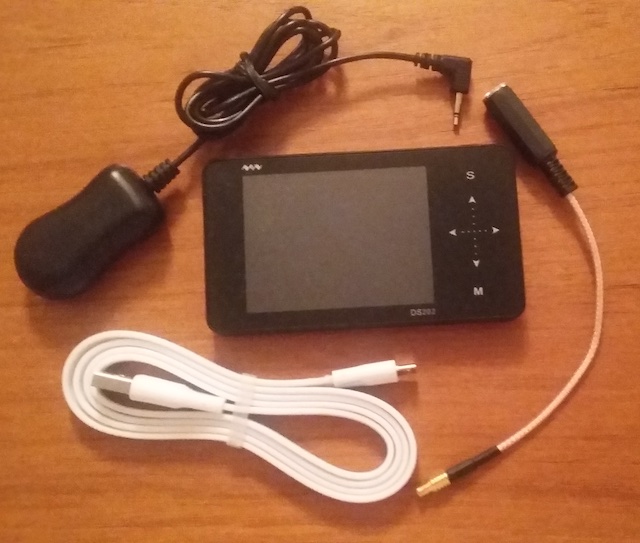
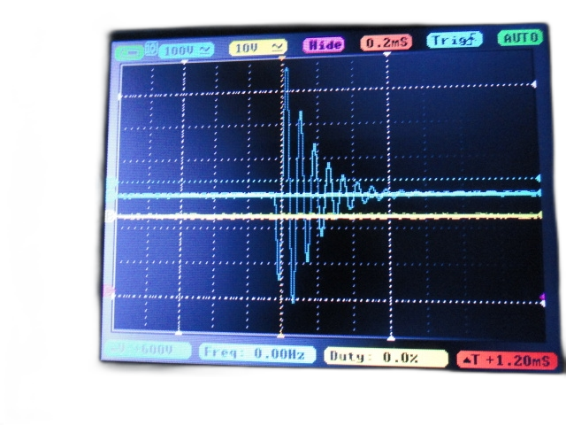
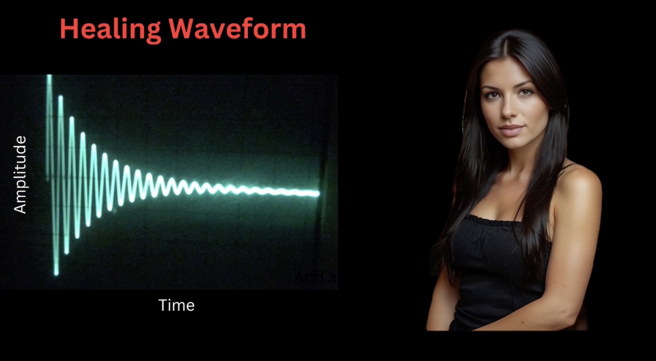
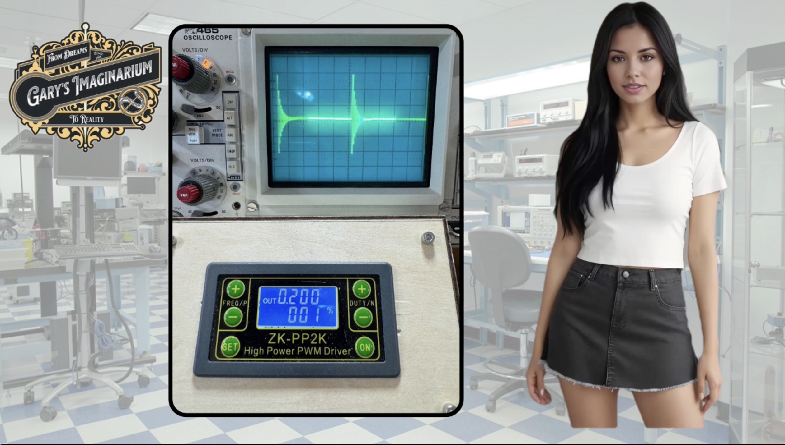
To achieve this, Gary assembled a PEMF Viewer, which is basically a EMF Sensor and a portable oscilloscope, enabling Bob and Ron to monitor both waveforms. Bob positioned a EMF Sensor connected to the oscilloscope near one of his active coils and captured an image of the generated waveform. This is the image it captured. |
|
|
|
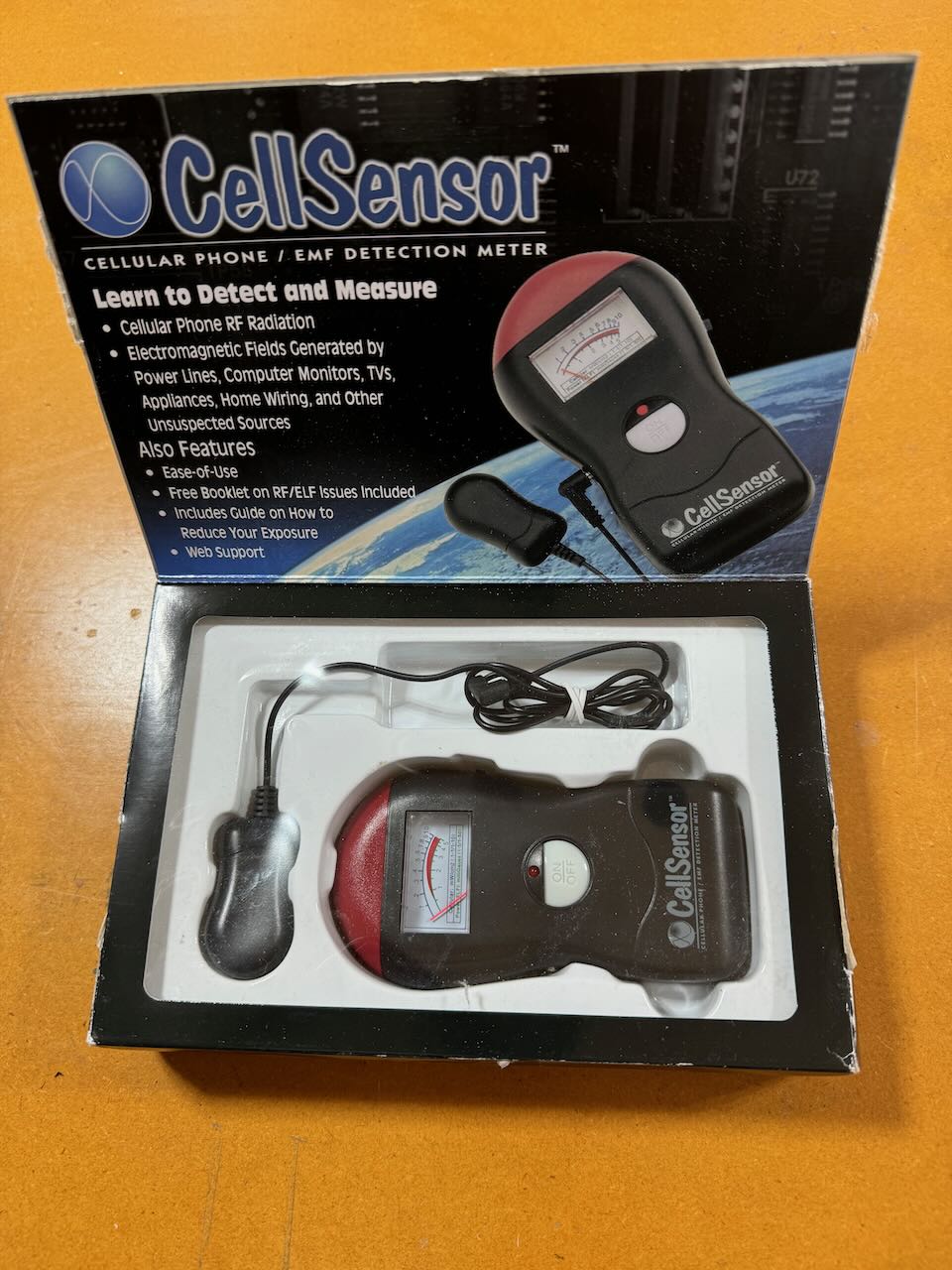
After Bob sent the Viewer to Ron for conducting a similar test, Ron confirmed that his device was not generating the same waveform. As a result, Ron returned his device to the factory for repairs. We did get a confirmation on the waveform that Ron's machine was emitting. I will show you that later when I show you the test results of the PEMF device we built. The EMF Sensor that Gary used for testing was part of a package called the Cell Sensor, and he originally purchased it from Amazon. We were going to provide a link below so you could purchase the Cell Sensor, but Amazon no longer sells it, however at the time of this video it is still available on eBay. Here is what the package looks like. |
|
|
|
To view the waveform generated by your PEMF device, simply connect the EMF Sensor to an oscilloscope and position it near one of your coils while it's operating. |
|
|
|
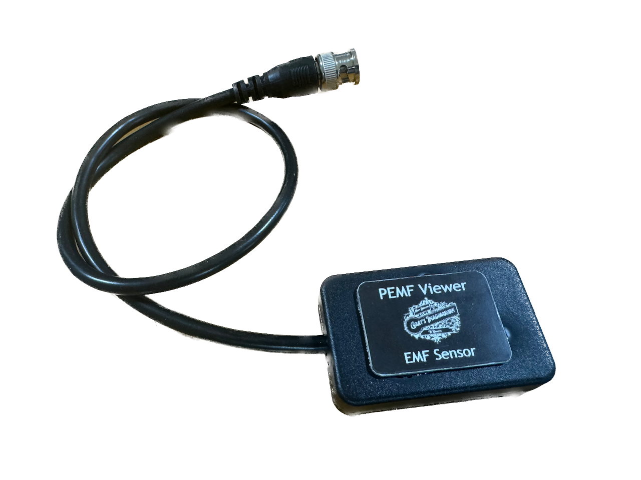
UPDATE September 2024: Gary's Imaginarium is building EMF Sensors and they're now available for sale. They are $49.00 each including USPS shipping. Description and Order Form |
|
|
|
|
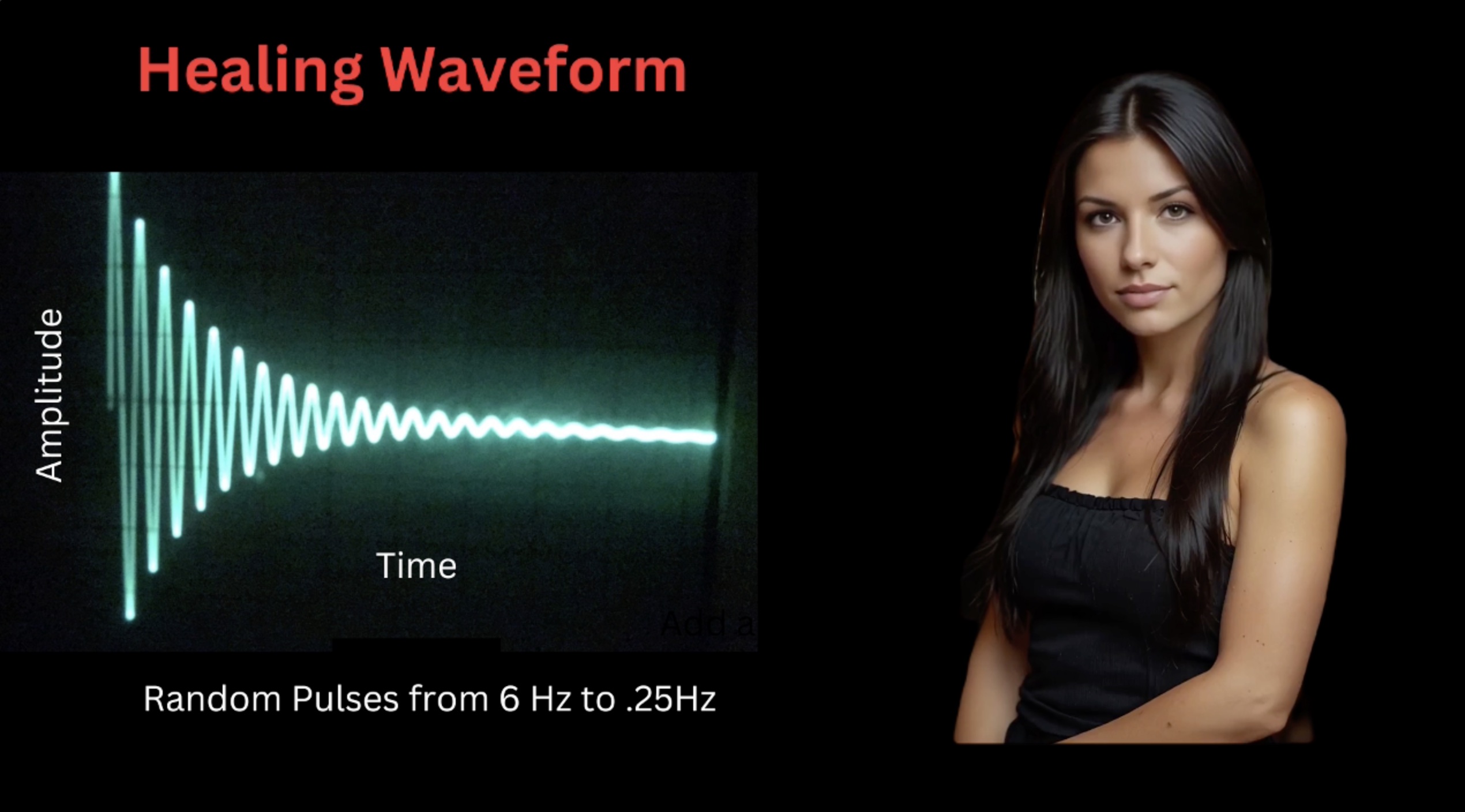
The "Healing Waveform" is characterized as a damped wave. This damped wave occurs when a magnetic field within a coil collapses once the power is deactivated. This collapse generates a back electromotive force (EMF), inducing a current in the coil in the opposite direction. This current, in turn, creates another magnetic field with opposite polarity, which also collapses. This process repeats until all the energy is dissipated and the waveform zeros out. Note that while the fields are collapsing the poles of the magnetic fields are also changing. Another analogy to consider is likening it to the ringing of a bell. When a bell is struck swiftly, it produces a sustained sound that gradually fades as the energy diminishes. If we were to examine the audio waveform emitted by the bell, and the "Healing Waveform" they would appear identical. |
|
|
|
|
This may be the reason this is a "Healing Waveform", because the body is receiving rapidly changing magnetic fields with opposite polarity. It should also be noted here that the frequency of the pulses in the professional PMT device is set to produce random pulses between 6.0 Cycles Per Second (HZ) and .25 HZ. This prevents the body from getting used to a steady pulse which makes the body's reaction more effective. |
|
|

|
It is important before we go any further is to explain Pulsed Width Modulation or PWM. PWM is a method used in electronics to control the amount of power delivered to a device by varying the width of pulses in percent in a periodic signal. It's commonly used in applications such as motor speed control and dimming lights. In the analog days if we wanted to dim a light bulb we put a resistor in between the bulb and power source. The resistor had to be rather large to able to dissipate all the heat that was generated. Using PWM there is no heat generated and no need for a resistor because we are only turning on the light in momentary pulses, the eyes can't perceive. Now it's let's have some fun and build a PEMF device. Since Gary has been experiencing back problems this spring, we can use the device on him and also do some testing. |
|
|

|
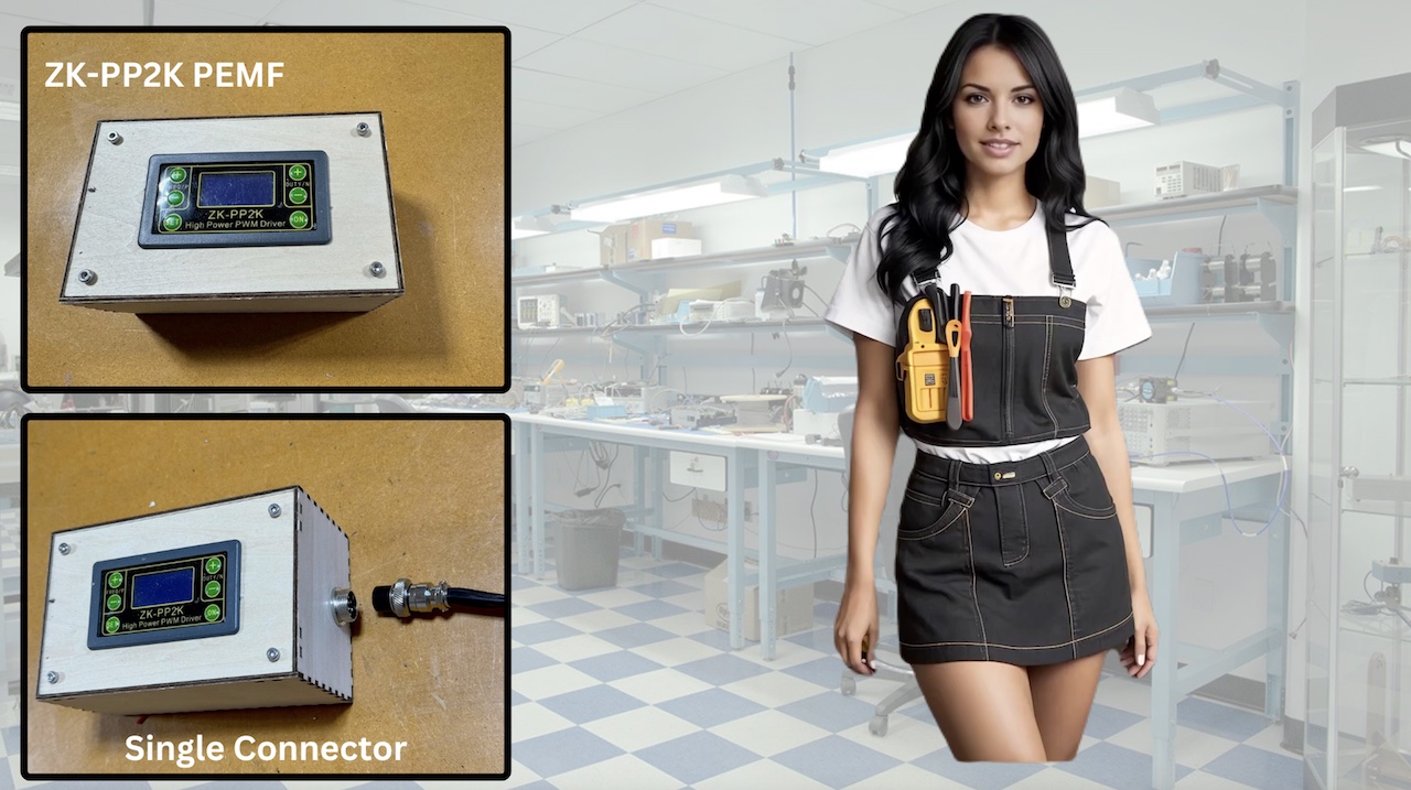
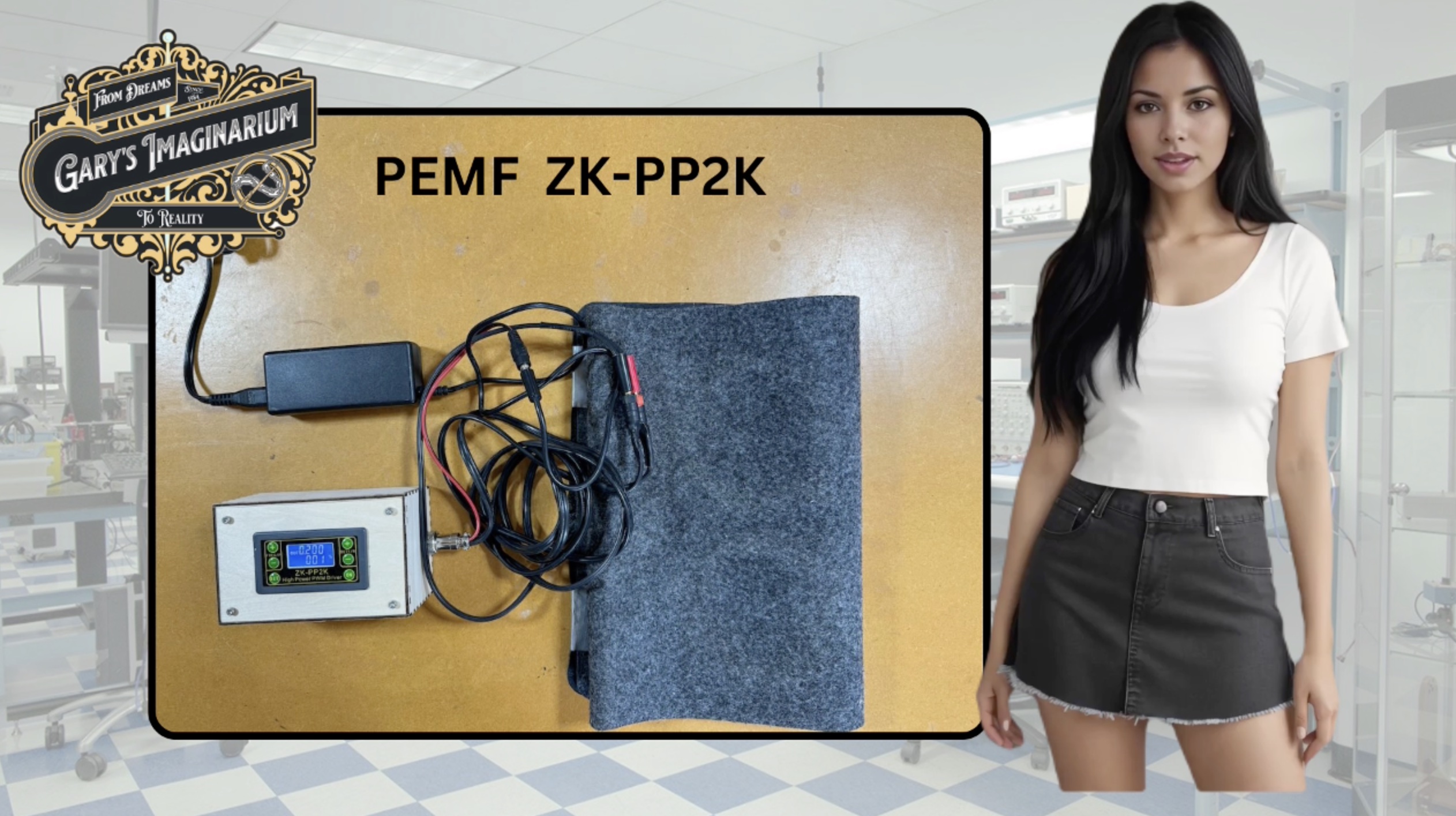
There are many YouTube tutorials available that explain how to build simple PEMF devices. One of these tutorials demonstrates building a PEMF device using a ZK-PP2K module. We will provide a link below to purchase the ZK-PP2K module. Here is the wiring diagram and a picture of the unit we completed. The completed unit consists of the ZK-PP2K Pulsed Width Modulator Signal Generator, a used 16 volt laptop power supply, and a 4-coil mat which we built. It is a good idea to save all those old power supplies. |
|
|
|
|
Gary utilized his laser engraver to fabricate the cool wooden box. We will be making videos on laser engraving adventures in the future. Note that the same connector is used for both the power input and the pulse output wiring to the coils. This enables us to connect the mat and power supply to various PEMF devices in the future. |
|
|
|
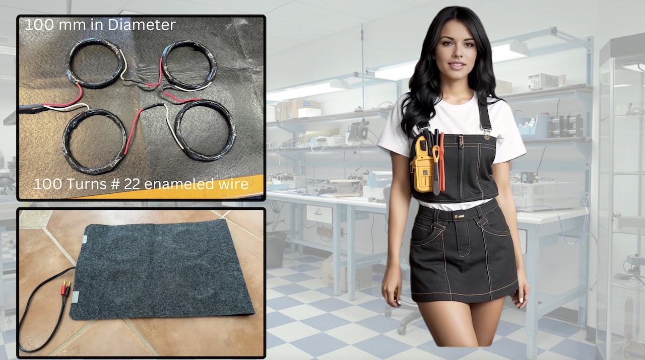
For the 4 coil mat, we wound the coils and taped them onto a mat as shown. Each coil measures approximately 100 mm in diameter and comprises around 100 turns of #22 gauge enamel-coated copper wire. We marked the coils inner and outer windings with red and white wires. Then when connected in series this will ensure that the tops of each coil will have the same magnetic polarity. |
|
|

|
We were really excited to use the Z K module PEMF device after the long building process, but our excitement quickly turned into disappointment when we began testing it to verify whether or not it was producing the "Healing Waveform". We were really glad we tested it before putting it to use ! After extensive testing involving various frequencies and PWM percentages, we successfully achieved the healing waveform using the ZK module, but only at one specific setting. We will highlight key findings you should be concerned with including Ron's waveform that was making people sick. For more detailed test results, please visit our website. |
|
|
|
Here are our Test Results
|
|
|
|
|
After documenting these tests, the final finding is that our four-coil mat achieves its best response with a 50-microsecond pulse, generating maximum gauss and the desired damped wave necessary for an effective healing pulse. It's important to note that achieving perfect inductance in a coil is impossible due to inherent capacitance, which determines its resonance frequency. The 50 microsecond pulse seems to ping the coil at its resonance, like the fine tuning of a bell. However, achieving this 50 microsecond pulse is only possible at 200 Hz when using the ZK, and if we switched it to pulse mode, the shortest available pulse is 1 millisecond. Furthermore, as previously mentioned, optimal healing requires producing pulses randomly between 6 Hz and 0.25 Hz. Therefore, the ZK-PP2K module and its Pulse Width Modulation are inadequate for ensuring the safe operation of a PEMF device. Consequently, we will need to incorporate a microprocessor like an Arduino to meet these specific requirements. |
|
|
|
Even though the test results indicated that the ZK module is not suitable as a PEMF device, we recommend building one yourself to discover the optimal resonance for your specific coil configuration. If you design it like we did with a single connector for both the power in and pulse wiring out, you can utilize the ZK module to determine the resonance of your coil set, and then integrate it into your final design by simply plugging it in. In the next video we'll cover the building of a safe PEMF device utilizing an Arduino microcomputer, using the same mat and power supply. |
|
|
|
|
|
This was a production of Gary's Imaginarium, "From dreams to Reality." Now for our quote for the day from Gary... "Imagination and creativity are the building blocks of the universe. Remember that everything you see around you started out as a thought first. Never stop dreaming." As always, thank you for watching. If you enjoyed the video please like and subscribe. |