
|
Welcome to Gary's Imaginarium, From Dreams to Reality. |
This transcript is from PEMF Video #2 on our YouTube Channel,
showcasing The Building of an Arduino Based PEMF Device
showcasing The Building of an Arduino Based PEMF Device
|

|
If you watched our last video, you would have seen us discussing the discovery of the healing waveform and testing a PEMF device made with a ZK-PP2K signal generator. In our findings, we conScluded that the ZK unit fell short as a PEMF device because it lacked the capability to deliver a 50 microsecond pulse and generate pulses randomly from .25 hurts to 6 hurts. I recommend you watch that first video before proceeding with this one. Today's video will guide you through the construction of a PEMF device using an Arduino Nano. We've received an order from a client for a 12-coil PEMF device, and we'll walk you through the entire build process. This includes assembling the control box, winding the coils, assembling the mat, and providing you with the Arduino code necessary to program your own PEMF device. We will also cover the process of determining the precise pulse width for this coil set to achieve the healing waveform with maximum amplitude and damping time. I will welcome you to our channel, then we'll begin with examining the schematic in detail. |
|
|

|
Hello, I am Gary's personal assistant Paula, and I would like to welcome you to Gary's Imaginarium channel. Where we will take you "From Dreams to Reality" using 3D printers, CNC machines, Laser engraving and lots of cool electronics projects. So let this adventure begin. |
|
|
|
|

|
In this video, we'll be constructing a PEMF (Pulsed Electromagnetic Field) device, commonly used in Pulsed Magnetic Therapy (PMT). This non-invasive, drug-free treatment is applied to various health conditions. PMT works by sending pulsating magnetic fields into the body, which replenishes depleted cellular energy to promote healing. |
|
|

|
|
A typical PEMF device consists of a mat or blanket with embedded coils that are placed on the body. The control unit provides pulsating power to these coils, creating a specific magnetic field that penetrates the body.
Let's get started! We'll begin by reviewing the schematic for our project. |
|
|

|
|
First let's go over the schematic we drew using a program called EasyEDA.
At the top left is the power supply. In this case we are using a 16 vdc used laptop power supply. The Power Supply positive lead is connected to pin 7, the negative to pin 9 which is the ground. Pin 7 then connects to an on-off switch which supplies the Buck Converter and the MOSFET driver. The Buck Converter supplies a reliable 9 vdc to the Arduino Nano thru the Vin pin. The IC2-2004 LCD display is linked to the Nano through connections for Ground, 5 volts provided by the Nano, SCL connected to A5, and SDA linked to A4. On D13 we have connected the LED through a 330 ohm resistor which will flash momentarily while the unit it pulsing. On D8 we have connected the trigger pin of the MOSFET driver. This will provide a 16 volt pulse to the coil mat. On D9 we have connected a single pole single throw switch which will determine the session time. If it is open the session will last 30 minutes, if closed it will last 10 minutes. On D3 we have connected the debounce circuit. D3 is designated as an Interrupt Pin. We have tried to use software to handle debouncing but it has never worked reliably, so we built a simple debounce circuit around a single pole single throw push button switch which will Start or Pause the session. You will need a 1.5 K and 15 K resistor and a .1 microfarad capacitor. The coil Mat contains 12 coils. 2 sets of 6 coils wired in series, then both sets connected in parallel. Total Mat resistance is 6.17 ohms, current draw 2.6 amps. Each coil is 95 millimeter in diameter with 130 turns of 22 gauge enamel coated wire. Estimated Gauss of 50. |
|
|
|
|
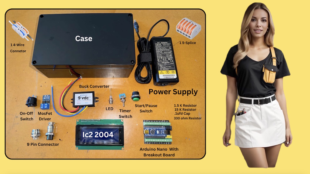
I have laid out all the parts on the bench that you will need for the project. There are links below for purchasing all these parts. You can of course substitute your own parts you may have in your shop. Starting across the top A 4 wire feed through lever connector. We have been starting to use these and they make for a beautiful layout in the project as you will see as we progress. The case, which has ample room for the project. The 16 vdc used laptop power supply. A 5 wire splice block. What to do with all your grounds, here is the answer. Across the middle: A Singe Pole Single Throw On-Off Switch. A Mosfet Driver. A 9 vdc buck converter. LED with a panel mount. A single pole double throw toggle switch for the session timer setting. You can opt to use a Single Pole Single throw switch. A single pole single throw, push button , start, pause switch. A one point 5 k, a fifteen k, and a 330 ohm resistor, and a .1 microfarad capacitor. Across the bottom A nine pin metal connector An IC2 2004 LCD display 4 lines by 20 characters. An Arduino Nano, with a breakout board. The breakout board makes wiring the Nano a lot easier. You can pause here or take a screen shot, otherwise we will move on to the layout. |
|
|
|
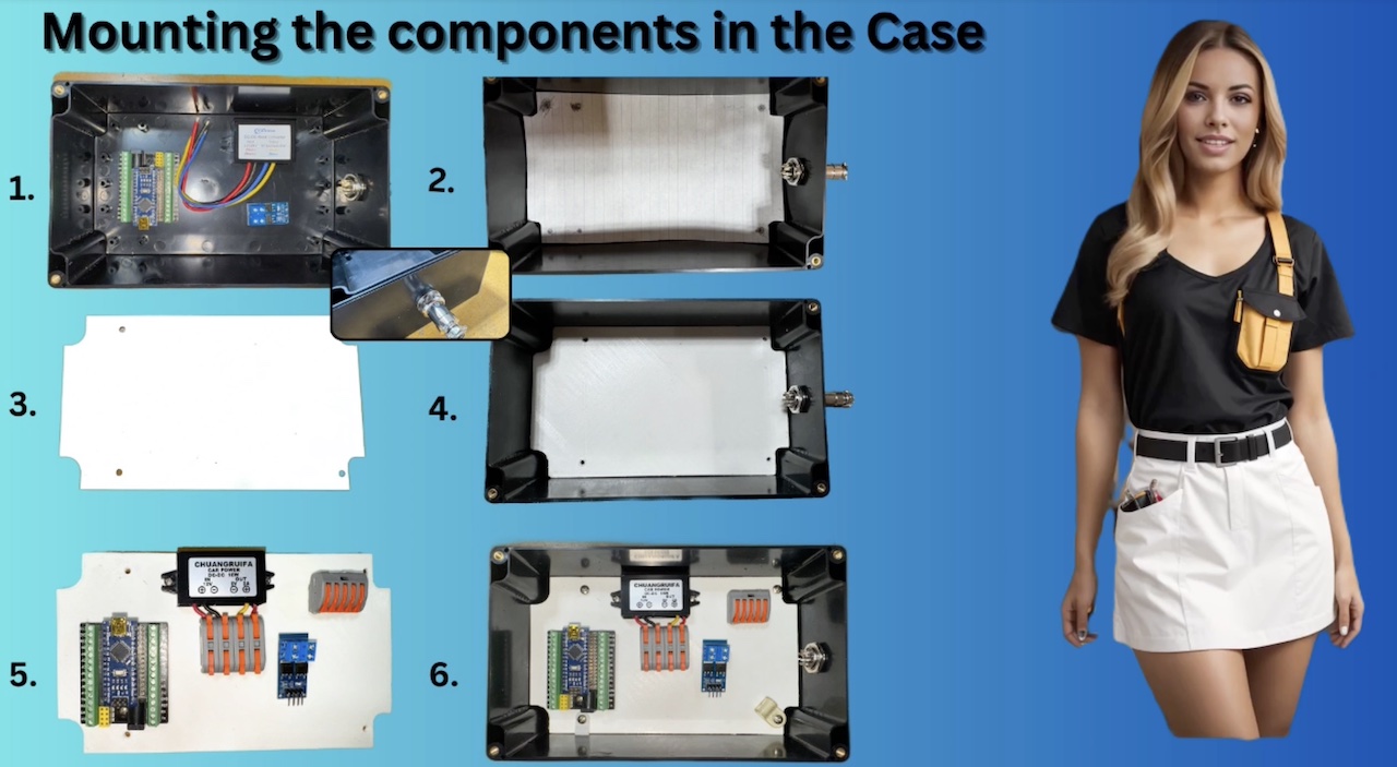
Mounting the components into the bottom of the case. I laid out the pictures of our progress and numbered them for reference. 1. As you can see we realized that to mount the components in the case we would need a bottom plate. The case has mounting risers so all we need to do is make a template and 3D print a plate. 2. We made a paper template, then used LightBurn and FreeCad to create a 3D Body. I will provide a link below for the SVG file in case you want to print one yourself. 3. The finished bottom plate printed in ABS. 4. Next is to make sure the bottom plate fits in the case. 5. Laid out how we were going to mount the components on the plate. We've shortened the leads on the Buck converter and inserted them into a 4 port Lever Wire Connector. Makes a neat job. For those of you who hate soldering this is the answer. 6. It seems everything will fit just fine. Sometimes opting for a slightly larger box can really reduce frustration. |
|
|
|
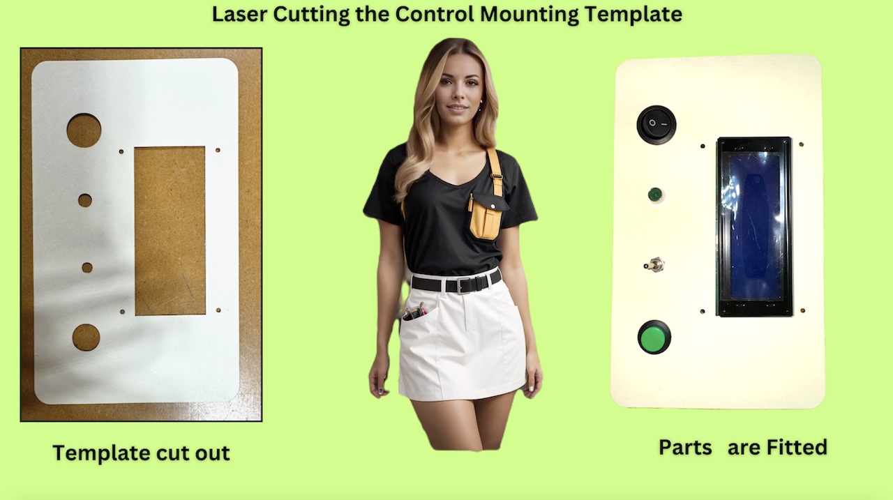
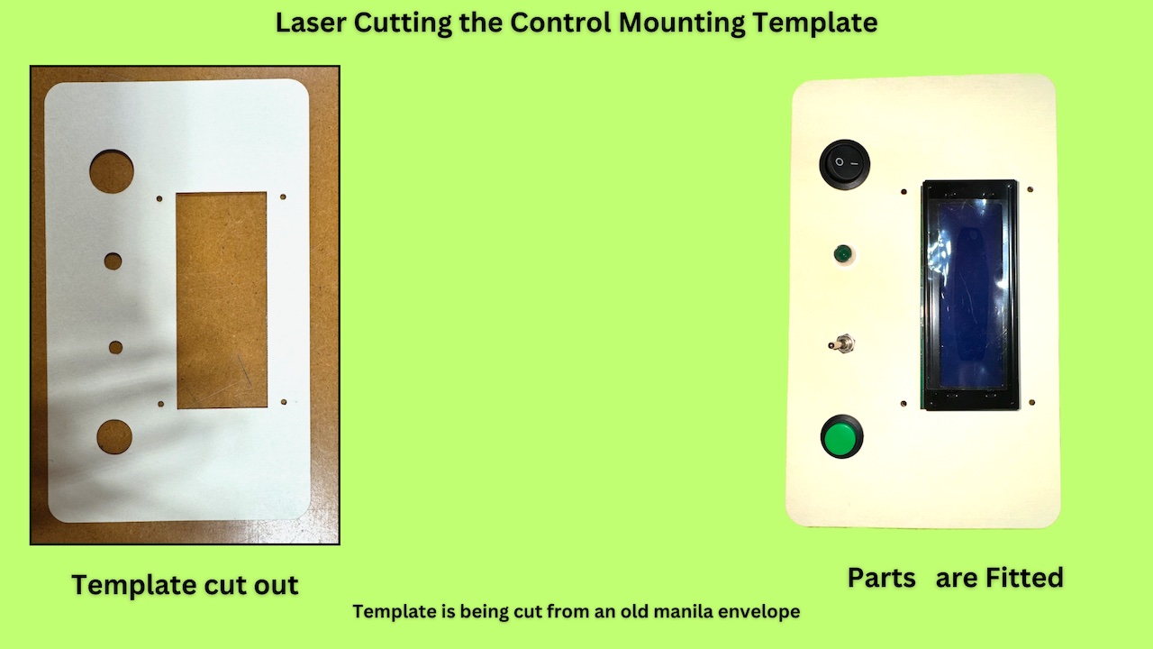
We want to mount the LCD, LED and the switches on the top face of the box. So the first thing to do is laser cut a template to make sure the spacing and the holes are all the correct size. We utilized LightBurn to design the template and perform the laser cutting. You can find the LightBurn file linked below. Now we'll watch it work at double the speed. |
|
|
|
|
|
|
|
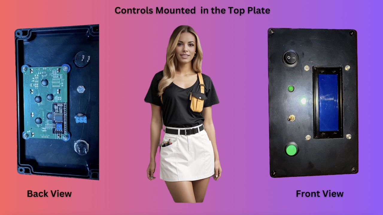
Now that the template is finalized, we need to use it to cut out the top of the case for mounting the LCD, LED and switches.
We exported the template as an SVG file from Lightburn and then uploaded it into Easel to configure the CNC cut settings. Next, we saved the project as a G-code file in Easel and loaded it into GSender to perform the CNC cuts in the top plate of the case. Here is a top and bottom view of the parts mounted on the top plate after the CNC machine did it's magic. Here is a short video of the CNC machine at work. |
|
|
|
|
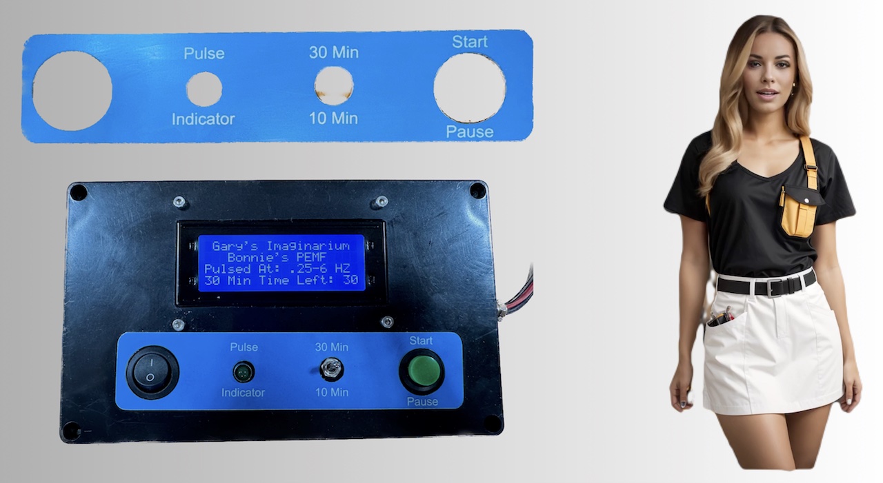
Now for the finishing touch, a placard to identify the control functions.
Using Lightburn we copied the file that we used for the previous manila envelope template and deleted everything except the switch cutouts. Then we made the switch cutouts larger to fit over the controls. Then we added the text and the outside cut for the placard. We put the laser to work, and glued the new placard on the box. How is that for coool. |
|
|
|
|
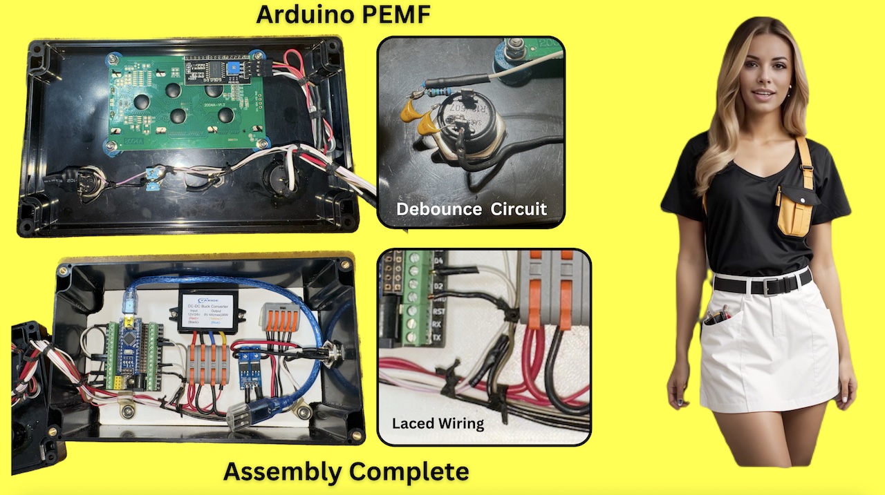
Here is the final assembly, all wiring is complete.
Here at Gary's Imaginarium we do not use zip ties in any of our projects. We use the old school flat, waxed, black lacing cord. Gary once wired a Turbo Lancair aircraft, opting to lace all the wiring rather than use zip ties. Also here is a closeup of the debounce circuit and how we simply mounted it on the switch and covered it with shrink wrap. As you can see I ran out of .1 microfarad capacitors and had to substitute two .2 microfarad caps in series. Have a look at the lever splice block where all the ground wires are joined together, and the lever connection block took care of wiring the Buck Converter. These blocks really enhance the neat and organized appearance of the project. We also left a USB cable in the box in case the firmware needs to be updated. Be sure to use the end cap that came with the cord so you don't short out anything. For wiring the Arduino we used the standard connecting wires with the connectors on each end. The male end goes in the Nano break out board and gets fastened in with the set screws. The female ends slides over the pins as shown on the back of the LCD. The only places we soldered were the 9 pin connector, and the control switches. We updated the firmware in the Arduino and tested the unit with our 4 coil mat and it works perfectly. Next on the list is winding the coils and assembling the 12 coil mat. |
|
|
|
|
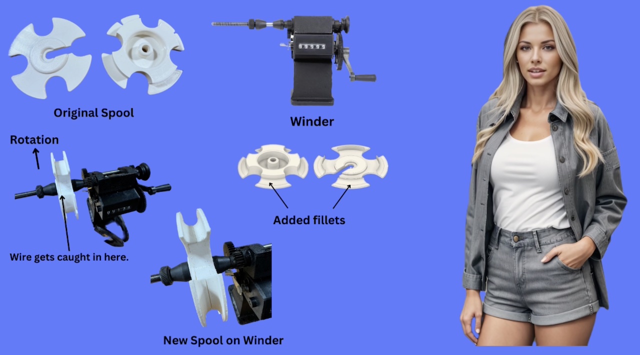
Now we need to wind our 12 coils.
We bought a winder from Amazon, which tracks the number of turns during the winding process. Some time ago, we downloaded an SVG file for a spool from the internet but can't recall the source. If you created the original design, thank you ! Please let us know, and we'd be happy to give you credit. This spool features four cut out sections, allowing you to secure the coil with tape at these four points before detaching it. To remove the newly wound coil, simply loosen the side piece and slide it aside. After that, you can easily slide the coil off the spool. It's a clever design! We printed the spool from the SVG file using Simplified3D, but encountered issues while using it. The side piece fits against the main hub, but it isn't tight enough, causing the wire to snag in the gap between them during winding. This is a mess, having to unwind all the turns until it can be fixed and started over again. Using Fusion 360, we designed a new spool with a filleted section on both halves as shown. This change allows the windings to be rounded off instead of flat when taken off the spool, and eliminates any grooves where the wire might get caught. |
|
|
|
|
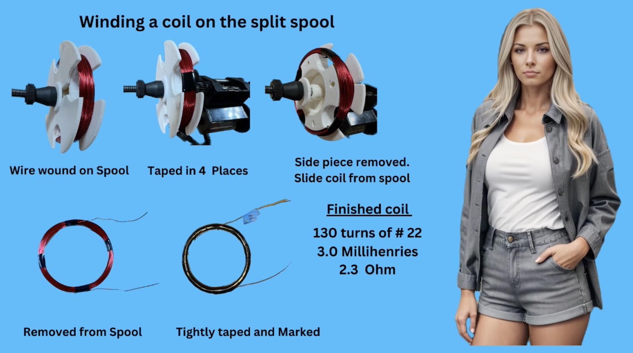
Here's how we wind the coils onto our split spool.
We use the winder to coil the wire onto the spool, stopping when we reach the desired number of turns. Next, we secure it by wrapping tape around the four open sections to hold it in a tight bundle. Then we remove the side piece and remove the coil from the spool. The final step is to wrap tape tightly around the entire bundle, then mark the bottom wire to track the polarity of the coil. Then we clean off the end of each wire with a flame, and measure the inductance and resistance. For our 12 coils of 130 turns of number 22 gauge wire it is 3.0 millihenries and 2.3 ohm. |
|
|
|
|
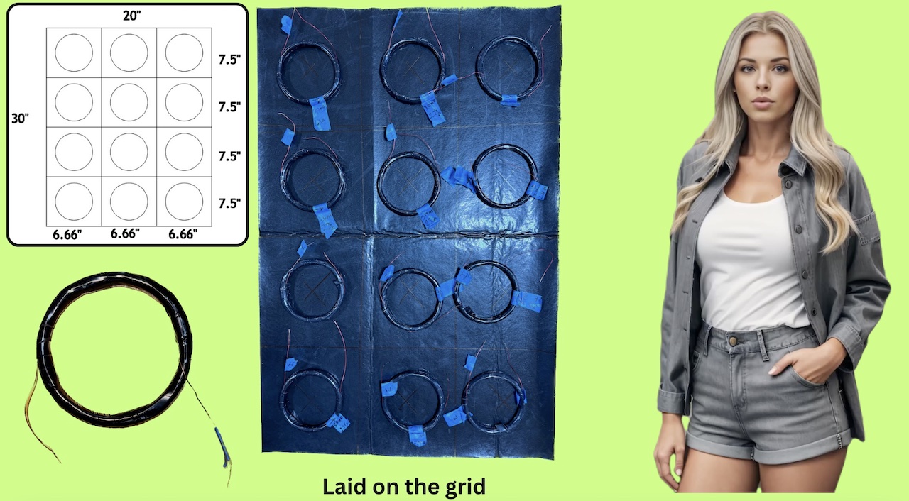
We cut the mat material to size, 30" x 20" then marked out the grid on the back according to the diagram we made using LightBurn.
To center the coils I marked an X in the center of each rectangle.
The material is easy to cut, with a smooth back allowing tape to stick. It is designed to be an "Under the Sink Mat". It has a finish side that is perfect for a PEMF mat. However as you can see it was very hard to mark. To ensure everything fit properly, we laid out the coils on the back side of the mat. We also checked that there was sufficient space along the edges for velcro to securely hold everything together. |
|
|
|
|
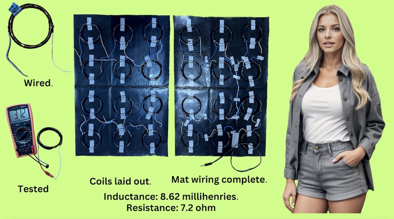
We soldered a 6" white wire to the coil's inner winding and a 6" blue wire to the coil's outer winding.
After verifying each coil for correct inductance, we affixed them to the mat using duct tape, orienting them so that all the coil windings were CCW, white wire on the right side. Then we soldered them all together with a cable leading out to a plug to connect to the control box. The total inductance for the 12 coil mat is 8.62 millihenries and the total resistance is 7.2 ohm. |
|
|
|
|
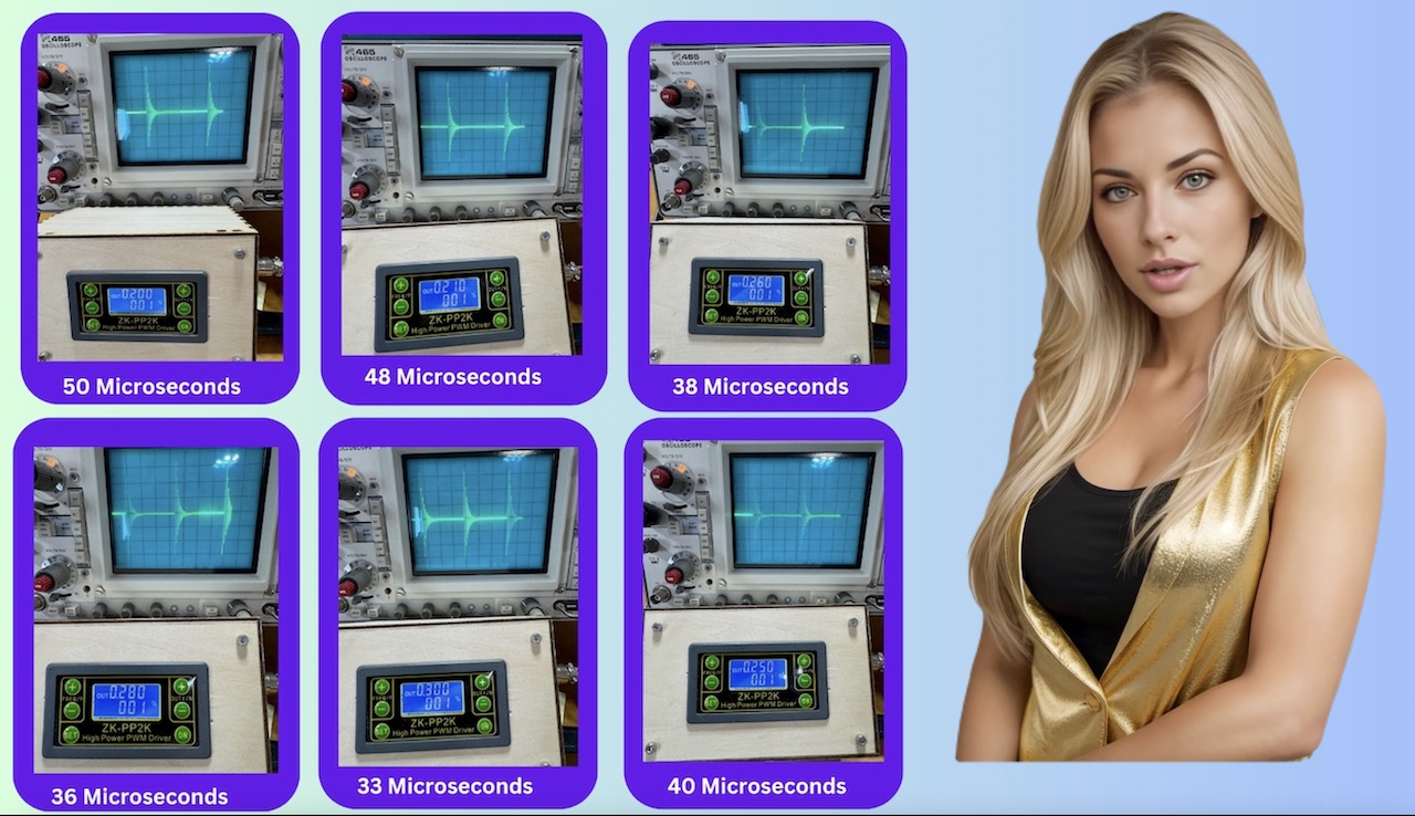
Now for the fun part, the calibration of the coil set.
We will be using the previous PEMF device we built using a ZK-PP2K module. As we mentioned in the last video we recommended that you build one in order to do what we are going to do next, find the resonance of this coil set. Top Left we started out at 200 Hz 1% duty cycle and you can that this is our "Healing Waveform". We went a little under 200 Hz to 195 Hz and the waveform deteriorated badly, so the 200 HZ 1% is just barely achieving our healing waveform at 50 microseconds. We went all the way up to 300 HZ at 1%, middle bottom, which is 33 microseconds and the signal started to decrease in amplitude. It is amazing on how linear this coil set is for a pulse width between 50 and 33 microseconds. Our last 4 coil set from our previous video only worked at 50 microseconds for max amplitude and decay rate. On this coil set the output is fairly flat at 48, 38, 36 microseconds with a slight increase around 260 HZ. At 250 Hz and 1% , 40 microseconds is the approximate center between 50 microseconds and 33 microseconds and this will be the setting for this coil set. We will update the firmware in the Arduino Nano so it generates a pulse width of 40 microseconds. This has also shown us that you cannot switch mats between PEMF devices without matching the pulse width to the coil set. |
|
|

|
|
The flow chart represents the Arduino Nano program that you can download in the description below.
The PMT session has 3 states, zero which is off, 1 which is running and 2 which is paused. The Interrupt Function is activated by the Start Pause button and simply changes the session state as follows. If the session state is zero, it is changed to 1, which is running and the display shows the "Time left in minutes". If the session state is 1, it is changed to 2 which is paused and the display shows "Paused". If the session state is 2, it is changed to 1, and the display shows the "Time left in minutes". When the session Paused or off there is not much to do but keep track of the timer. When the session is running, the display shows the "Time left in minutes". it then updates the Time Left, turns on our L E D for about 2 Milliseconds, then gets a random delay time, then after the delay it sends the pulse. The total session time is set by a Single Pole Single Throw switch to choose either 10 minutes or 30 minutes. |
|
|

|
|
We are thrilled to announce the completion of our Arduino-Based PEMF device, designed to emit the 'Healing Waveform' and it is now ready for PMT, Pulsed Magnetic Therapy.
Throughout this project, we employed a laser engraver, 3D printer, and CNC machine, giving you an overview of how these machines can save you a lot of time working on these type of projects. The laser engraver cut out the template to mount our controls, and it engraved the placard. The 3D printer printed out the base to mount our components into the box. Additionally, the CNC machine was used to cut out the openings in the top of the box to mount our controls. After watching our presentation, we are confident that you have the capability to construct one of these amazing devices on your own. |
|
|
|
|
|
This was a production of Gary's Imaginarium, a channel devoted to turning dreams into reality."
Now for our quote for the day from Gary... "Even though the Universe is infinite, our creativity expands it even further.." As always, thank you for watching. If you enjoyed this video presentation please like and subscribe. |