My Kossel Clear Calibration Procedure
It has taken me over a month to build and calibrate my Kossel Clear and after all this time I have finally been able to print a good object. Some of the calibration techniques are OK but for me none of the single set of instructions worked for me. So I put together the best of all the techniques I found and added one or two myself. Hopefully I can save you a lot of time between completing your assembly and getting a good print.
Before calibration it is assumed you have done all the pre-calibration tests to make sure the printer is working correctly.
Step 1: Go through all the videos and calibration text you can find on the Blue Eagle Labs web site to familiarize yourself with all the procedures. Then finally view this video provided by Blue Eagle Labs.
Step 2. Now that you have familizerized yourself with all the procedures we will start with calibrating the Z0 position of the nozzle. In the last video he went through the procedure of setting the X0,Y0,Z0 position and then making the correction in the Marlin firmware. Do this procedure and make sure you heat up both the bed and the nozzle before calibration. Remember that the sheet of paper underneath should be just touching the nozzle and the paper should have a slight resistance to movement.
Step 3: Forget the auto calibration for now because the X, Y and Z "0" height positions must be done next.
It is really difficult to have a correct auto calibration if all the end stops are not set before hand. The auto calibraion should considered an added extra benefit to correct an unlevel bed.
Follow his procedure in the video to align the X, Y and Z end stops, but without running the auto calibration.
With our modification we did to the end stop screws, you'll have to loosen our 2 added nuts before doing the adjustment. Be sure to tighten them again after your adjustment. One turn of an M3 screw is about .1mm. Because we preset them earlier you should be making only 1/4 to 1/3 turn adjustments at a time. Nozzle too high; move the screw up; too low; move the screw down.
If you were way off you may have to do Step 2 again and then step 3 until all positions are correct.
Step 4: Now calibrate the auto-calibration. Start with a setting such as G29 Z2.0 and you should end up high. (The Z parameter in the G29 code line is the distance from the tip of the nozzle to the top of the calibration micro-switch.) Repeat the auto-calibration G29 code with different Z parameters and do the paper test at the X0,Y0, Z0 position until it seems right. Now check each of the X, Y and Z positions and you'll see that they are the same as the X0,Y0, Z0 position because we set the end stops earlier. Now run a test print, like my Test Block as shown below.
Download my test block if you want to match it to the pictures below. Download TestBlock.stl and set it to print 15 lines of brim. I've been using Cura because it is a much easier program to use. Edit the start code for each test print and set different G29 Z parameters until the print looks good.
Once you see enough of a print to make an evaluation, stop the print, enter new code and try again.
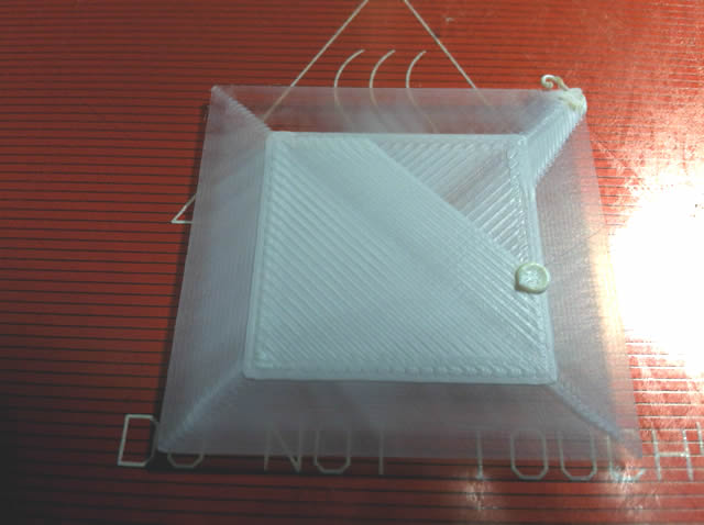
| My test results.... Easy Fill 1.75mm Filament (MakerGeek.com); Head 230c, Bed 110c, Object:TestBlock.stl |
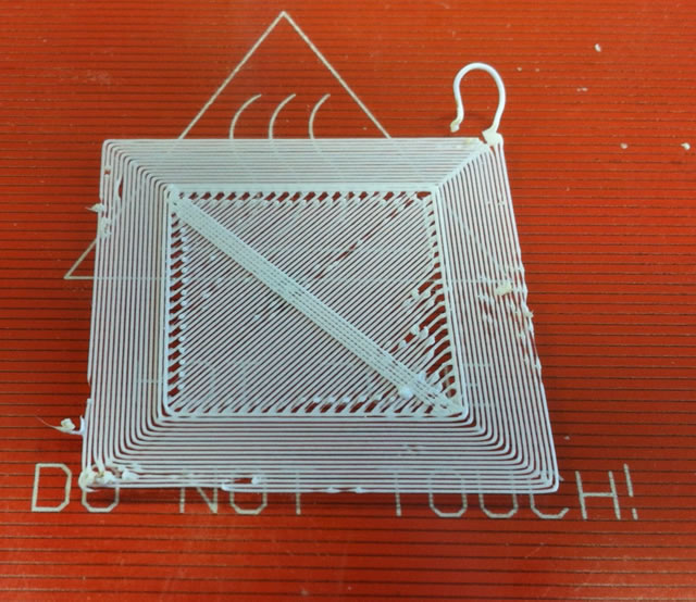 |
| G29 Z1.7 Hot Head too far from plate |
 |
|
 |
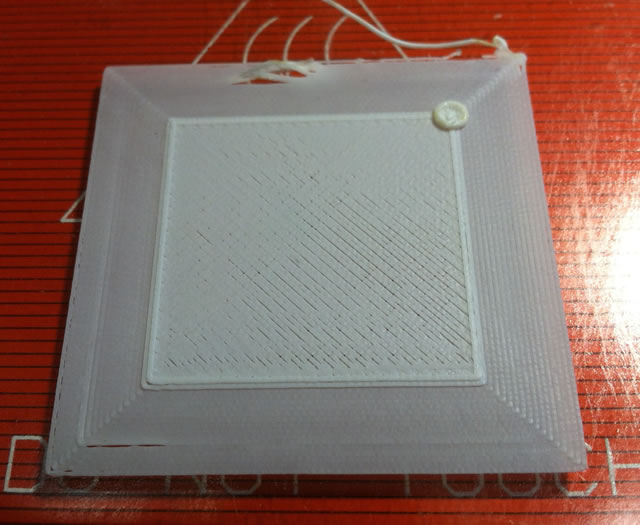
| G29 Z1.55 Too Close... Extruder feed kept clicking. |
 |
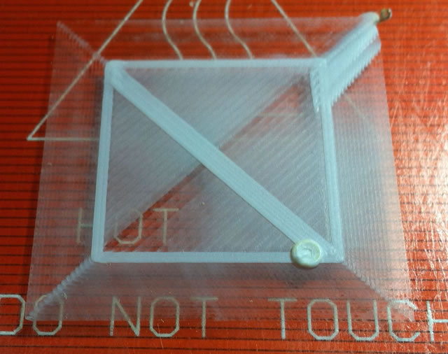
| G29 Z1.57 Still too close. Extruder feeder clicking. |
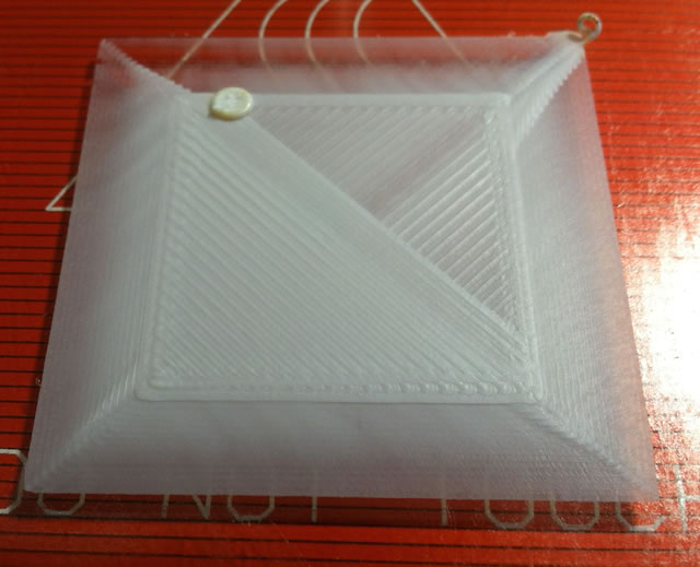 |
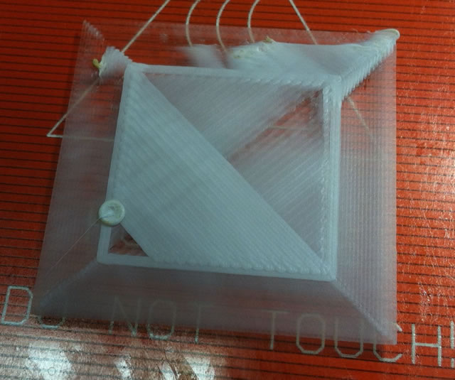
| G29 Z1.58 No clicking on Extruder Servo Notice the brim is more filled out. |
 |
|
Depending on your printer you may have to tweek a different end stop, either up or down.
once the setting is done you will notice that all three axis on the print are now the same.