 |
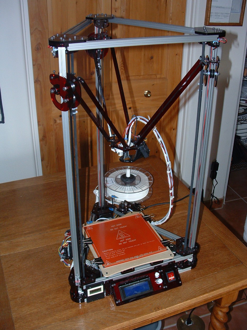
| Fully Assembled |
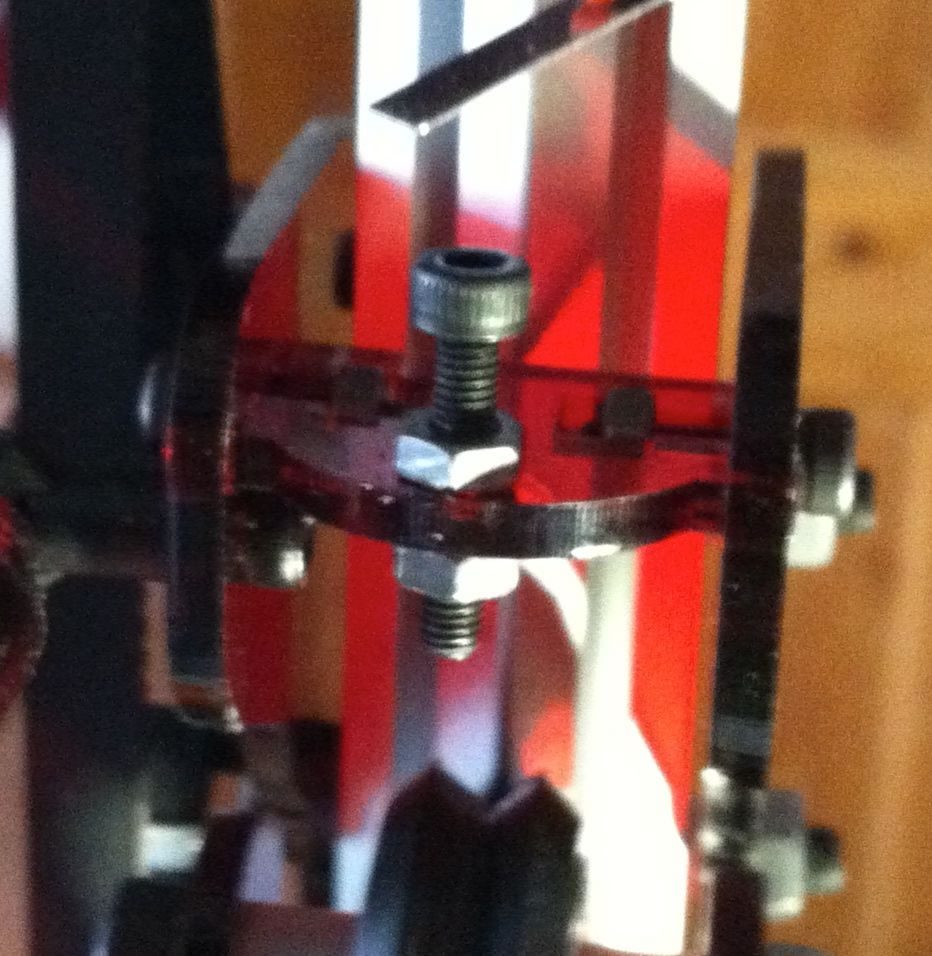 |
| End stop adjustment screws mounted to acrylic bracket with 2 M3 nuts. |
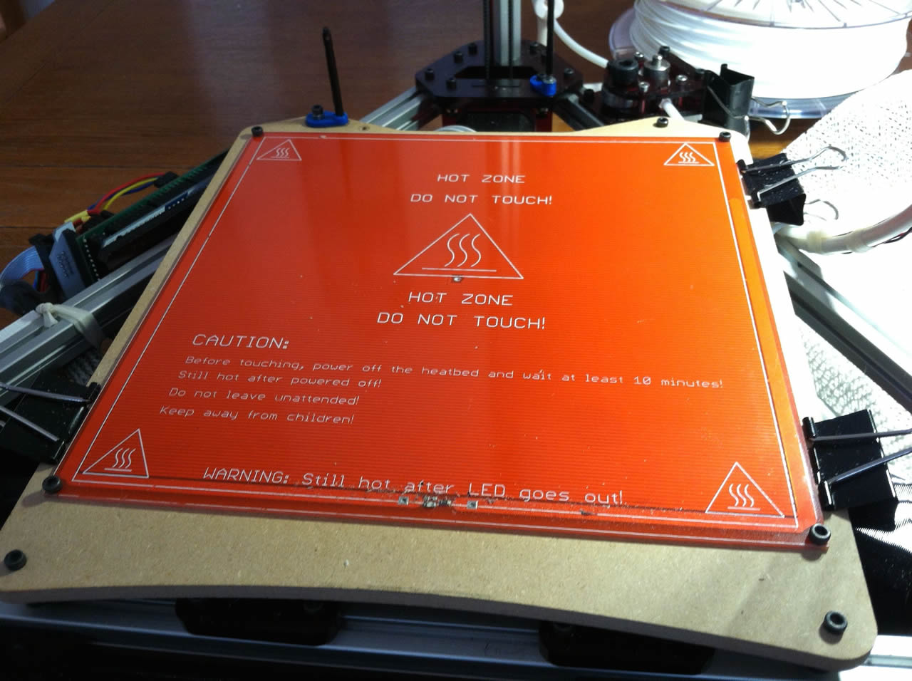 |
| MK2 PCB hot bed |
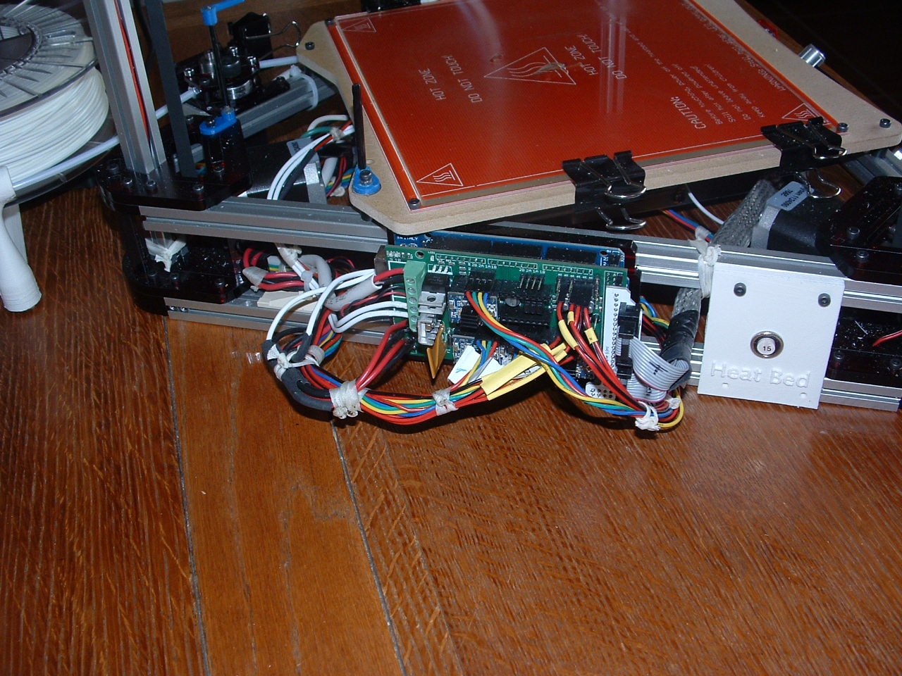 |
| Left side showing the Ramps 1.4 and Arduino with my added 15 Amp circuit breaker. |
 |
| Ramps Board showing Polyfuse and connector block removed. |
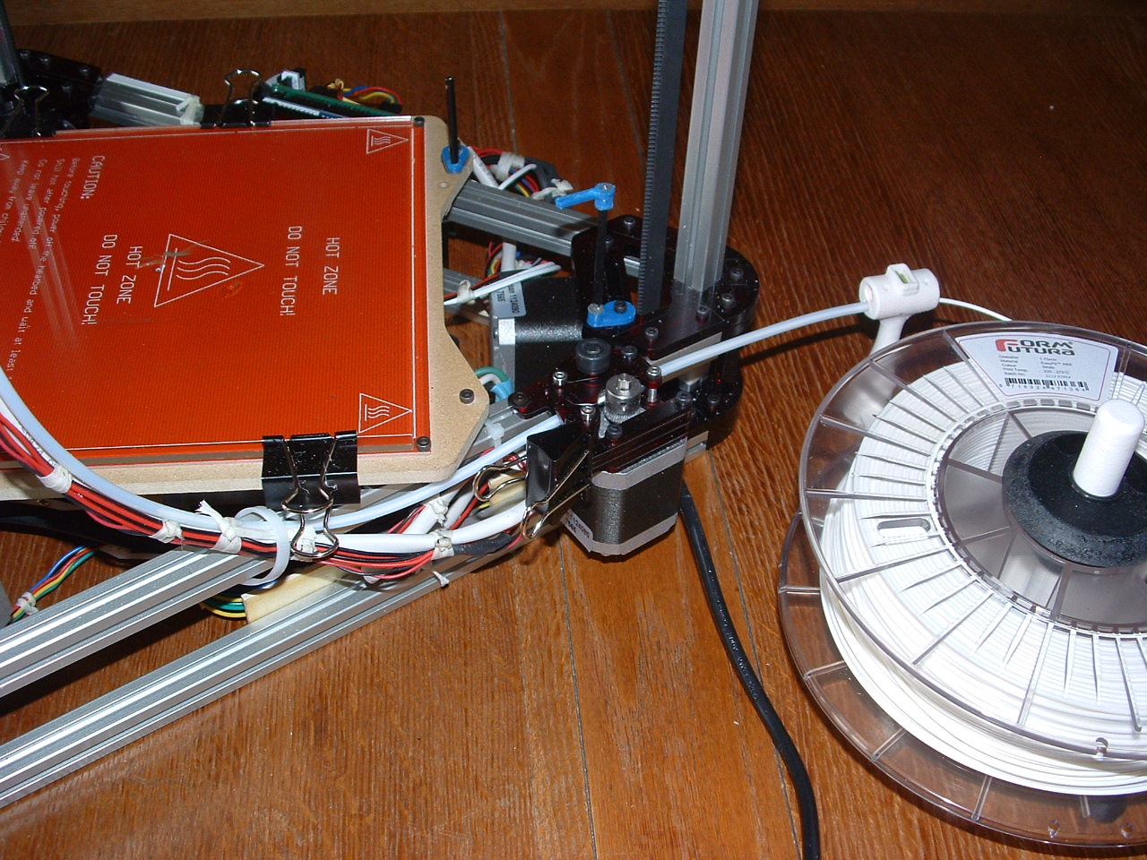 |
| Right side showing the extruder. The filament spool feeder was printed. |
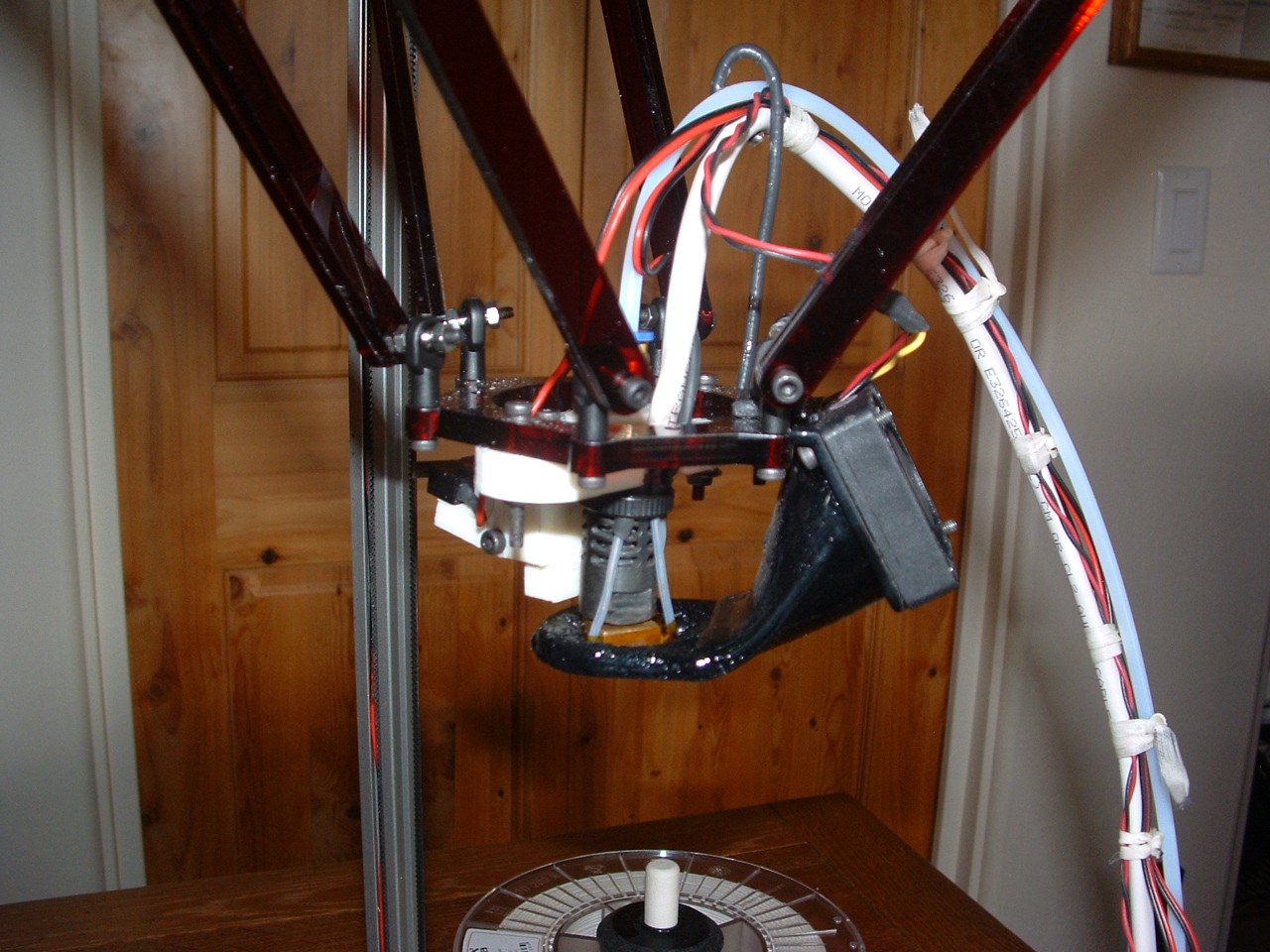 |
| Fan and fan duct mounted |
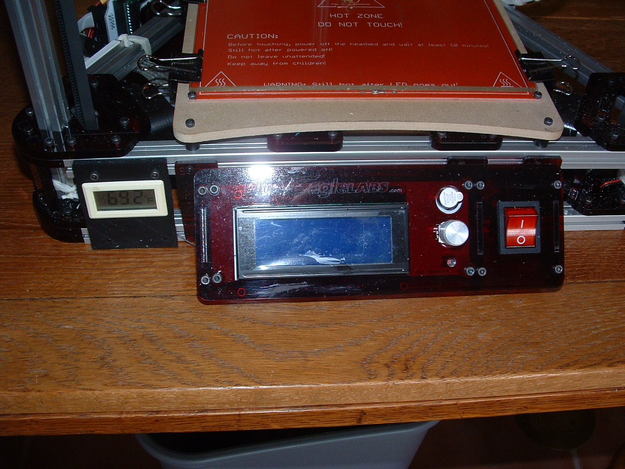 |
| Front side showing the LCD and just for fun I added a temperature indicator salvaged from an old computer. |
Building the Kossel Clear
I chose a Kossel Delta printer for a number of reasons.
-
From an engineering standpoint I think it is much more accurate when printing an object from the bottom up to have the printing head move up instead of the whole bed moving down.
A heavy bed moving down in increments is not as accurate as a light print head moving up. The bed gets heavier as the object develops and it needs to be kept as level as possible. - When the bed is moving down you have a limited max height for the object, while a solid bed with a moving print head going up can make for a much larger object.
- A solid bed can can be leveled once and you are good to go for many prints, no worries on it getting out of calibration like a moving bed.
I chose the Blue Eagle Labs Kossel Clear printer for a number of reasons.
- I liked the fact that they built the unit out of laser cut Acrylic parts.
- It is also larger then a lot of Kossel Deltas out here. Most of the other makes are called Kossel Minis. The Kossel Clear sides are 16 3/4" and it is 29 3/4" high.
- I was able to get the LCD accessory with it so you can print from an SD card. Don't buy one without it.
- It comes with a solid 6mm high hard board or masonite as a base for the hot bed.
Unpacking the kit.
After I unpacked the printer from the box I laid it all out on the work bench. I took a careful inventory of all the parts and found I was missing some. If you find parts missing email Blue Eagle Labs right away. It took over 2 weeks before they finally shipped my parts. Communication skills are also wanting, as I was never kept in the loop until they shipped them. I guess I was impatient but after spending a lot of money I wanted to get it up and running as soon as possible. I think we are all guilty of that.
Building the kit.
I followed all the videos on how to build the unit and there are a few mistakes in the instructions and what things are called. I'm from the old school and have been building airplanes and boats all my life, and I guess I'm picky when "screws" are called "bolts" and good soldering techniques are shown not so good...
Issues
Spare nuts on the rails:
Front Side: 3 on the bottom and 3 on the top of the side slots. Add 2 extras top and bottom in case you need to mount anything later. You can loosen the top rail to insert the nuts but the bottom rail is a lot of work to get them in once it is together.
-
Left Side: 2 at the top and 2 at the bottom of the side slots. The instructions mention 2 more on the top slot of the top rail. This is for the Extruder. I mounted mine on the other side so i was shy these on the right side. I would recommend you add 2 on each side so you can chose later on what works best for you. also add 2 more nuts on the side slots top and bottom in case you need to mount something later.
-
Right Side: 2 at the top rail top slot for the extruder, in case you need to mount it on the right side. Also 2 on the top and bottom side slots in case you need to mount anything later.
End Stop Adjustment Screws - Refer to picture on the left.
This was the major problem with calibrating the printer. Each time I printed the settings were never the same. Each time I calibrated to the best of my ability, the next few prints were way off. So after a long night of noodling the problem I tightened up the belts and inspected the end stop screws.
In the video instructions we are instructed to install M3 10mm screws. Yikes! They were barely holding into the acrylic because they were not long enough and to mount them by threading into the acrylic was not the best design. They had already stripped out the threads in the acrylic and were sitting sideways in the hole.
This is a critical part of the design to maintain the accuracy of the printer.
So my fix was to use a M3 16mm screw and back it up top and bottom with M3 nuts.
I calibrated the unit once again and my prints are coming out perfect. What a difference!.
FYI.. My final measurement was 13mm from the bottom of the acrylic bracket to the top of the screw head. Before calibrating you should initially set them all to around 11mm. This will ensure you will be higher off the bed for the first tests.
All my final adjustment measurements are between 12.48mm and 13.27mm.
MK2 Hot bed Mounting - Refer to picture on the left.
-
In the assembly video we are instructed to tape the thermistor under the MK2 PCB and squish it between the it and the mounting plate. No way was I going to do that. The thermistor actually goes into the hole in the middle of the MK2 PCB. I also added a bit of thermal heat sink compound (available at Radio Shack) to distribute the heat around the thermistor.
The MK2 PCB mounts with the LEDs on the top side.
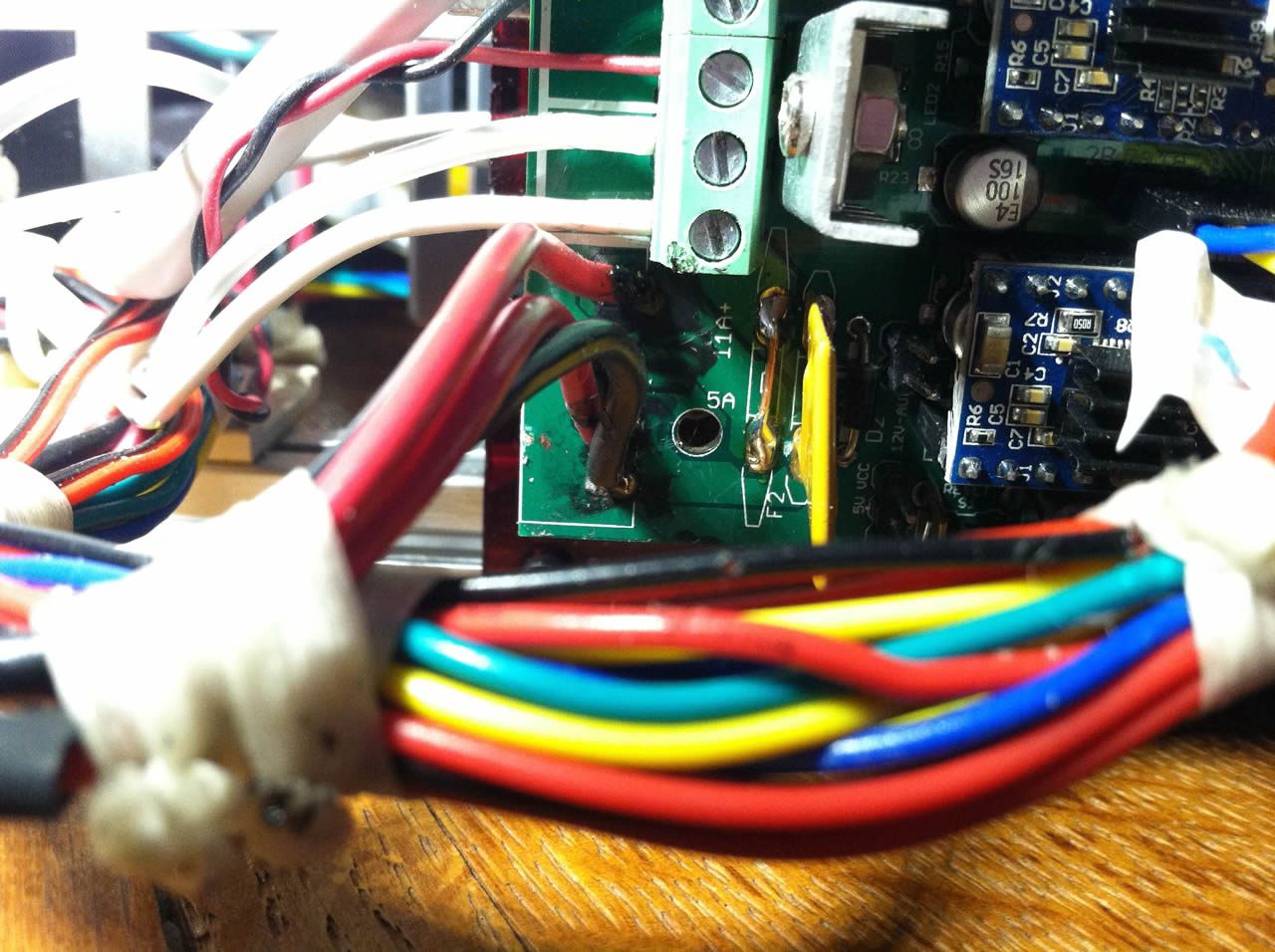
Ramps 1.4 Board - Refer to picture on the left.
-
When I measured the resistance of the PCB it was 1 Ohm cold. As it heats up the resistance will get higher, 1.6 ohm at 110c but on the initial start it will require full amperage. According to Ohm's Law; Current = Voltage/Resistance which is 12 / 1 = 12 Amps. The Poly fuse on the Ramps 1.4 board is only good for 11 Amps. This was causing my hot bed to keep shutting down during a print.
I inspected the power connector on the Ramps and it was melted under one of the pins from the power supply. So the connector is also a weak link.
I removed the connector and wired in molex pins and sockets, then replaced the poly fuse with a wire and installed a 15 Amp circuit breaker in the power supply feed line. I printed the circuit breaker mounting plate and installed it on the left side.FYI.. If hot bed thermistor is not connected the hot bed will not turn on. After doing the mods it wouldn't work and I anticipated major problems with my work. However I noticed that the thermistor became partly unplugged during my rework on the board.
Extruder - Refer to picture on the left.
I mounted the extruder on the right side because there really wasn't any room on the left side. When you do this the extruder will be going backwards. You need to change the direction it goes in the firmware, do not switch the plug around. Go to Configuration.h and zip down to line 302 and change it to read;"#define INVERT_E0_DIR true"
Fan ? - Refer to picture on the left.
I found I could not get a good print without a fan. The hot plastic would bunch up and then be melted some more as the head came back around. In other words the plastic wasn't hardening enough before the next layer. I had the messiest prints ever.
I found the coolest looking fan shroud on Thingiverse http://www.thingiverse.com/thing:455865
I downloaded it, imported it into Sketchup and it was a mess. Spent a long time correcting empty polygons and this is the best I could do. I changed the top bracket to fit the Kossel Clear.
You can download it here. Download Fan Duct stl
Use the following settings in Cura and print it. The print temp will depend on your filament. Change what you must to match your printer.
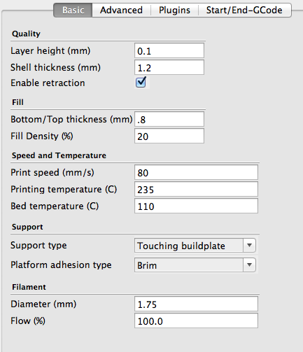
Once it is printed I had to add some epoxy glue to the top in order for it not to crack because it comes out a little brittle.
To install the fan you need to wire it to the Ramps 1.4 board between the Hot Bed wiring and the Hot Head wiring terminals. See the wiring diagram provided by Blue Eagle Labs.
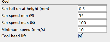
To setup the fan in the software go into Ponterface and run a direct command such as M106 S127. The S setting is the speed and not all fans run at low settings. The S speed goes from 0 to 255. Keep entering M106 code S speeds until the fan just runs, then add a bit more. I started at lower settings until the fan ran.
Once you have this setting you must enter it in your slicer as a minimum fan speed by percentage. My minimum S speed for my fan was 90, so 90/255 is 35%. In Cura go to the expert settings, compute your percentage and enter it as shown below.
NOTE: If you intend to print and use this fan duct you must move the auto-calibration micro-switch to the other side of the flap. Look closely a the picture and you will see it is now on the top of the flap.